When I first tried putting my Ford Type 9 gearbox into my Locost I realised that the gearstick was going to be too far away from my hand, and risked a collision with the dashboard. I looked around for designs for gearchange extensions and realised that none covered all my needs - hence this design.
To be exact, my needs were:
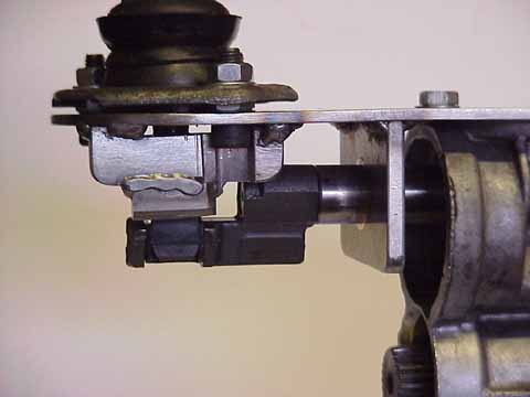
Looking at the gearchange mechanism I realised that everything revolved around the gear selection shaft. If this was extended by the required amount (in my case, 5 inches) and supported properly the normal gearbox functions could operate correctly (reverse detent and reversing light switch).
Note that a lathe is required for making most of these parts. It is also necessary to adjust the gear lever, as described by Dave Andrews - with the added bonus of converting the mechanism to a "quick shift"!
This is quite simple, as long as nothing is rusted, jammed or broken!
The mechanism is now stripped and ready for the next stage.
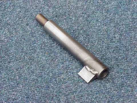
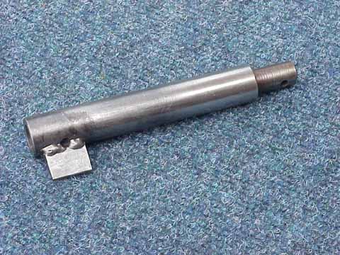
This is the key component of the mechanism and everything else either hangs off it, or supports it.
This is a length of round mild steel bar with a hole at one end and a reduced section at the other. The selector lever fits on the reduced end, and the hole fits over the end of the gearbox selector shaft. Roll-pins hold everything together through two 5mm holes that are drilled parallel to each other.
Note the piece of metal welded to the "hole end" of the shaft - this operates the reversing light switch. The working surface of this piece was case-hardened to reduce wear. If case hardening is not required then the piece can be brazed to the shaft instead of welded.
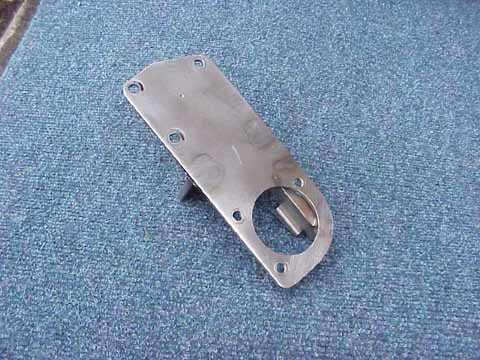
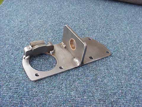
This is made of 3mm steel plate, and its only purpose is to hold the selector shaft rigidly in relation to the gearbox. There are two parts: the main plate and the bearing support plate. These are welded together for strength and rigidity.
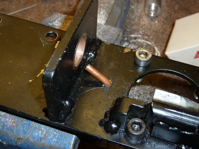
The bearing is made of phosphor-bronze and sized to match the diameter of the selector shaft (a "good but easy" fit). This bearing is fixed into the support plate using Loctite 603 retainer.
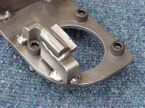
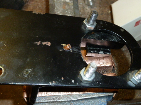
When I first planned to make the detent I considered shaping a piece of metal to match the original detent. I then realised that this was foolish, as I had the original detent that was made from a prime piece of hardened steel. I decided to grind off the upper part of the detent and weld it to a backing piece, which was in turn welded to the supporting frame.
The size of the backing piece was easy to identify - its position was a matter of trial and error. The two parts were clamped to the frame until first and second gears were easy to engage, but reverse wouldn't engage until the gearlever was pushed down. Once the position was identified the pieces were fully welded.
It is necessary to modify a couple of the parts taken off the gearbox: The bottom of the selection lever had to be ground off to ensure that it cleared the universal joint of the propshaft, and a hole was drilled in the metal cover plate to allow the gear selector shaft to pass through. This helps to keep dirt out of the original chamber.
After using this for a while I realised that I would need to lubricate the bearing - and that is difficult to do without removing the mechanism. I needed to remove the extension to do some maintenance so took the opportunity to fit a small piece of brake tubing so that the bearing can be oiled easily without the need for dismantling anything. This tube is wide enough to take the spout from a can of white grease, or a few drops of oil.
Hopefully the following pictures will make it clear: