The process of fitting bike carbs to my crossflow engine took longer than I expected, so I decided to re-fit the original Ford-fitted Weber carb that had been used on the car for several years. Unfortunately I had already modified the Megajolt ignition unit to use a TPS (Throttle Position Sensor) so I either had to unmodify the unit, or fit a TPS to the Weber carb. As I still intended to use bike carbs eventually I decided to fit a TPS.
After a bit of head-scratching and puzzling I decided that the easiest location for the TPS was at the end of the throttle linkage, where the accelerator pedal cable connected. The objective was to set up a link from the connecting rod to a TPS mounted on a rigid bracket.
A suitable TPS and connector was found in a scrapped Ford Escort dated around 1990. This was located on the front of the engine on the driver's side, and was easily removed by undoing 2 screws and cutting of the connector from the loom, leaving as much wire as possible on the plug.Note that you must get a sensor that operates the right way round - with the D-shaped hole facing you, the rotor must be spring-loaded anti-clockwise, and operate clockwise.
Nearly all of the remaining materials came from B&Q: One steel angle bracket intended for joining timber and one piece of 8mm diameter aluminium rod. The other part was a short length of 10mm x 15mm rectangular section aluminium, but B&Q's finest 10mm square bar would be OK if drilled with care.
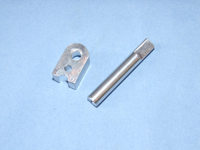
The first part to make is the piece that is fixed to the carb throttle linkage. The rectangular section is cut and drilled as shown in the following picture:
Note that the semi-circular groove at the base is filed once the piece is offered up to the end of the linkage, to fit over the lump at the back of the cable connector (this stops it twisting). Also note the small recess one the linkage side of the piece - this is to allow for the small amount of waste metal found on the side of the flat linkage plate resulting from welding (a bit of filing of the waste metal may also be required).
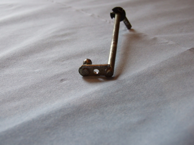
Once this piece is complete it can be fitted to the throttle link: clamp the two pieces together firmly and drill a 4mm hole into the flat linkage plate. You should now be able to fix the 2 parts together with a M4 nut and bolt.
At this point the connecting bar can be made: cut an over-long piece of 8mm diameter aluminium bar and carefully file a flat at one end, 12mm long. The thickness between the flat and the other side of the bar should be 6.1mm across the whole length - so make sure that you file it evenly! This D-shaped end should then fit into the hole in the TPS; if it doesn't, carefully file the flat a little more until it does.
First the bracket is reduced to 60mm on each side of the 'L'. After tidying up with a file it is lined up with the edge of the existing throttle linkage bracket on the rocker-cover side (away from the throttle cable). You should now see that there is a weld on the existing bracket that stops the new bracket from lining up nicely. Mark the position of that weld, draw a line to the corner of the bracket and hacksaw/file the excess away. You should now be able to line up the two brackets properly - hold them in line, turn them over, and mark the two holes with a felt-tip pen. Locate the centres as close as possible, centre-punch them and drill to 8mm diameter.
Cover the inner face of the vertical leg with marking blue (or permanent felt-tip will do at a pinch). Make a pointer from an offcut of the 8mm rod, either in a lathe or by spinning it in an electric drill and filing it to a point; the only requirement is that the point is central to the rod. You will have to experiment with the length - the idea is to put the pointer in the connector hole, assemble everything and use the point to mark the face of the bracket, but it may take a few attempts before it's right. Once you've found the spot, dismantle it all, dot-punch the mark you've just made, and measure off for the TPS mounting holes. Once everything is marked and punched, drill one big hole for the sensor (mine had a 15mm locating collar) and two 4mm holes for the mounting screws.
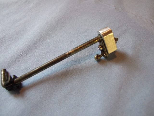
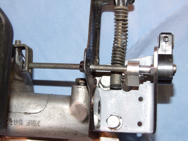
The last step is to install the 8mm bar with the D-shaped end. Assemble the bracket, push the 'D' into the sensor, then try the sensor on the bracket - at this point the rod should be too long. Estimate the amount by which it is too long, take it out, and cut the excess off. I would recommend that this is done in small stages as it is easy to cut off too much. Once the length is correct, turn the sensor away from its locating holes anticlockwise by about 5 degrees when looking at the back of the sensor, and mark the rod and the connecting piece. Take it all apart and fix the rod into the connecting piece, carefully lining up the marks you have just made - I used Loctite 603 to fix the two together, but I'm sure that epoxy resin and/or a roll-pin would also do the trick.
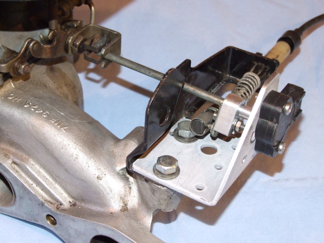
The only part that needs any treatment is the new steel bracket - this should be rubbed down, de-greased and sprayed with your favourite paint (I used black Plastikote). Once it has dried properly, assemble all the bits and pieces leaving the two mounting bolts slightly loose. Push and pull the brackets until everything is lined up nicely and the throttle linkage operates the TPS without strain or binding. Tighten the fixing bolts, re-check the alignment, and the job is done.
| [Weber DGV 32/36 carburettor menu] |