For several years after first registering the car I managed without a windscreen, prefering to wear a crash helmet; this was fine for a while, but started to get tiresome on hot summer days when the helmet became stuffy and uncomfortable. It also made occasional trips to the pub more troublesome - we always had to decide whether to risk going without a helmet for a short journey, or whether to get kitted up and have to find somewhere to store the kit when we'd arrived.
For these reasons I decided that I would fit a windscreen. Unfortunately, exchanging the original 'Brooklands' flyscreens for a windscreen isn't a simple replacement job - there are other things to consider:
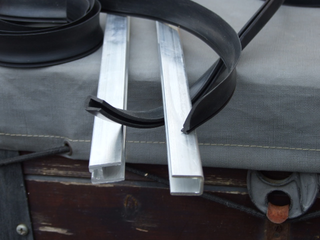
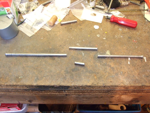
The first challenge is to find the right materials: although it is possible to use extruded aluminium channel from B&Q, it is better to try and find the 'right stuff' that has a rounded profile on the top part, and a channel to hold a rubber seal on the base part. The raw materials can be seen below:
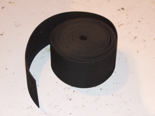
The aluminium sections can be bought from Arch Motors and Manufacturing Ltd in Northampton - they make chassis for Arial and Caterham, but will sell materials if you ask them nicely (they are fairly cheap, too!) - and the 50mm x 1.5mm rubber strip came from Woolies.
I actually started to make my own windscreen frame - and decided that it wasn't as easy as the book made out, made a bit of a mess of it, and eventually decided to have one made.
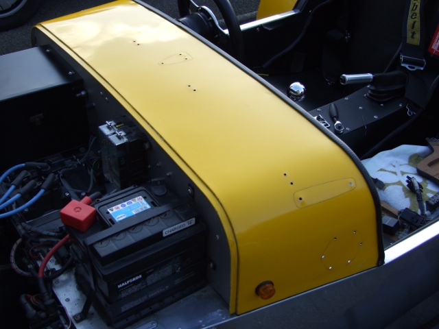
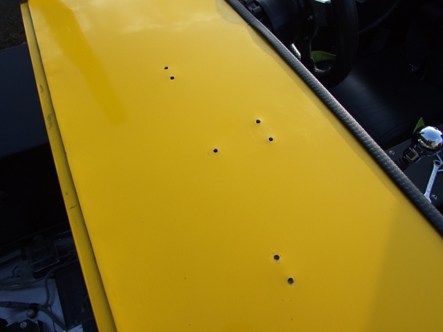
The first task was to strip all the bits and pieces off the scuttle, such as the Brooklands screens, mirrors and tax disk holder. This left quite a number of holes to be fixed!
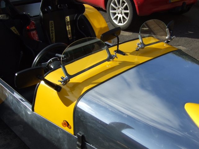
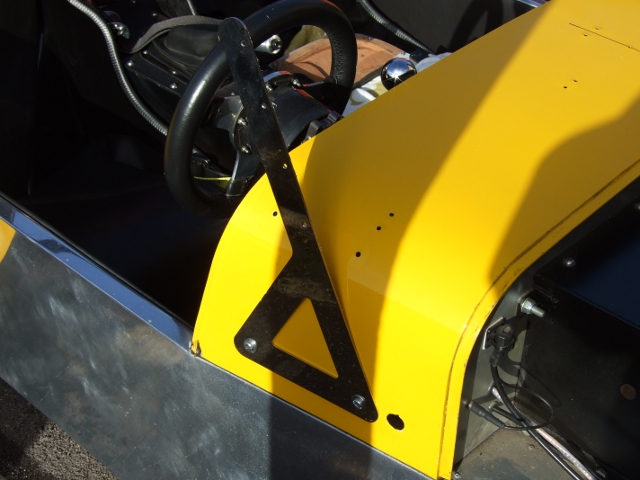
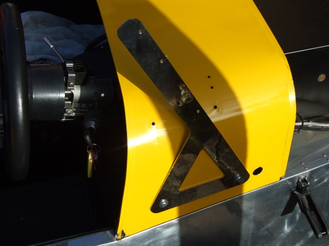
The next task was to fit the screen supports to each side of the scuttle. These supports were laser-cut out of nice shiny stainless steel - a bit of luxury as I could have made them myself, but maybe not out of stainless and probably not as pretty.
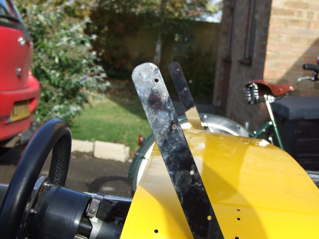
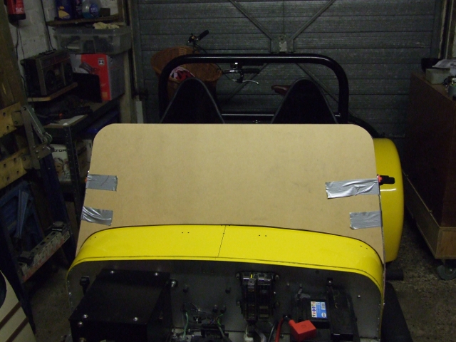
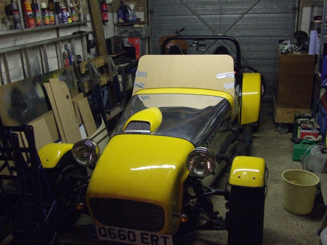
These were lined up after considerable research into where everyone else had put them, and with some consideration for the planned screen height. The first one was fixed in its intended location, then the other was lined up to match; this involved getting the fore-and-aft position correct, then a bar was put between the mounting holes and checked to ensure that it was level. Finally the alignment was checked by sighting across the upper arms as a rough guide, then a flat piece of MDF was placed across the front of the uprights to ensure that they were in line (it would not be possible to bend a glass windscreen into position!)
The screen template can be made once the supports are fixed into their final locations. This template was to be sent to the frame maker, so it had to be accurate: the arrangement was that the template was to be the exact size of the outside of the frame, without allowances for frame or mounting rubber thickness, and made out of 9mm MDF.
First a cardboard template was made to match the curve of the scuttle between the two uprights. Once a good shape was made it was reversed and re-tried to ensure that it was symmetrical - although the scuttle wasn't expected to be. This shape was then transferred to a piece of 9mm MDF that was slightly larger than the eventual windscreen shape.
The MDF was then lined up with the windscreen supports so that a pencil line could be drawn - this then showed the width of the screen. The MDF was cut along these lines (slightly over-size) and the edges trimmed, planed and sanded until the template was a good fit between the uprights.
Finally, the height of the screen was drawn onto the template - this was done by clamping the MDF between the uprights, sitting in the car and deciding on the minimum height for clear vision. After ensuring that the top line was horizontal when the template was in place, the top corner curves were marked; these were approximately the same radius as the top of the roll bar, purely for the sake of making it look right.
The template was then carefully packed up and shipped to the frame maker.
My new frame arrived with the trimmed template inside - this in turn would form the basis for the glass-cutting template - and with some rubber sealing strip. The frame was disassembled into its 2 parts: the top section made from U-section, and the lower section made from a more complex extrusion (U-section on the top, and a T-slot section underneath). The MDF glass-cutting template was set aside for safe keeping.
The T-section rubber sealing strip was fitted into the slot under the lower section of the frame and cut several inches over-size at each end to allow for later trimming.
The frame was then re-assembled without glass and clamped in place between the 2 uprights on the scuttle. Some effort was then taken to get it positioned correctly - pushed down so that the rubber made a good seal against the bodywork (but not too tight, to allow the rubber seal to flex properly) and nice and level when sighted against the roll bar (the most obvious reference point on the car). Once it was located correctly the frame mounting holes were marked through the holes in the uprights. The hole positions were centred and re-checked a few times, then drilled to take the mounting studs. After fitting the studs the frame was ready for the glass.
First make sure that the frame is totally symmetrical, with the bends and angles matching on each side, before creating the template for the windscreen! Some good-quality art-board was used to make the template, using the original MDF template as a starting point. This was fitted into the frame and trimmed until there was about 3mm clearance all around. This was passed to a local windscreen repair shop so that they could cut cut some genuine 6mm laminated car windscreen glass to match. Make sure that you get the template back - you never know when you'll need a new windscreen. My screen came with the supplier's identity etched into one corner, together with the code for the relevant BS standard; this is not enough for IVA as they specify that the standards mark should be 'built-in' rather than etched - but as my car had already passed that stage I was happy to accept the cheaper option!
I then fitted the mounting studs and checked that the frame was clean, free of burrs and ready to take the glass. The 50mm x 1.5mm rubber sealing strip was cleaned, folded in two and slid it into the frame, leaving a reasonable amount of spare strip at each end. Holding the frame with the open end upwards, the glass was lowered into the channels, pulling and pushing the seal until the glass slides in - 3 or 4 hands are useful at this stage. Some effort was required and the glass had to be pushed quite hard, so good strong gloves were an essential safety precaution (probably safety glasses too). Don't use any lubricants such as soap at this stage, as it just makes a mess, everything gets slippery, and it may cause the rubber to rot later on. If something is sticking a bit then some talc or french chalk will help (try a bike puncture repair kit). The rubber ended up all rucked and crinkly in the corners, but this wasn't a problem as it was due to be trimmed later. Some duct or parcel tape was used to hold the assembly together, then everything was carefully set aside while the rest of the frame was prepared.
The lower part of the frame was checked, the T-shaped seal refitted underneath, then another length of rubber seal was folded and fitted in the top groove. The rubber on the ends of both parts of the frame had to be trimmed so that they could be put together. After more pushing and shoving the lower part was pushed onto the glass and the fixing screws inserted (this part did take some time, as the glass has to be fully into the frame all round before the screws could be fitted and tightened). The remaining rubber seal was cut away prior to the final installation, once I was certain that everything was OK.
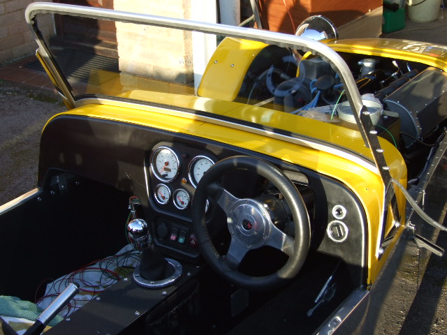
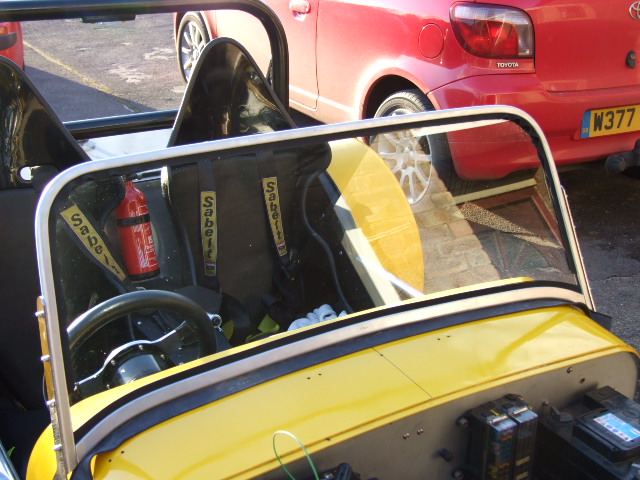
The completed screen was then offered up to the supports and the fixings were tightened up, ready for fitting the wipers.
Like many other car builders, I bought an ex-Mini 2-speed wiper system. This was originally made by Lucas and is known as the 14W model. It has a simple mechanism, is very durable and spares are still available. Unfortunately it also has a few 'issues' - mostly to do with the wiring and the tubes that hold the flexible drive rack.
The Lucas wiper has a strange wiring diagram - there's no other way to describe it - intended to continue to provide power to the wiper motor until it's parked after use. This means that you cannot use a simple 3-way switch to control it; originally it had a special Lucas switch that made the necessary connections, but that was expensive, didn't really fit in with my wiring loom layout and looked ugly.
I did some research on the internet and found a few solutions - some were a bit dubious but one appeared to be a possibility. This was redesigned to use earth switching (0v on the switch operated the relays) which meant that the heavier cable required by the motor could be much shorter - the long wires to the switch only had to carry the relay coil current, which is minimal.
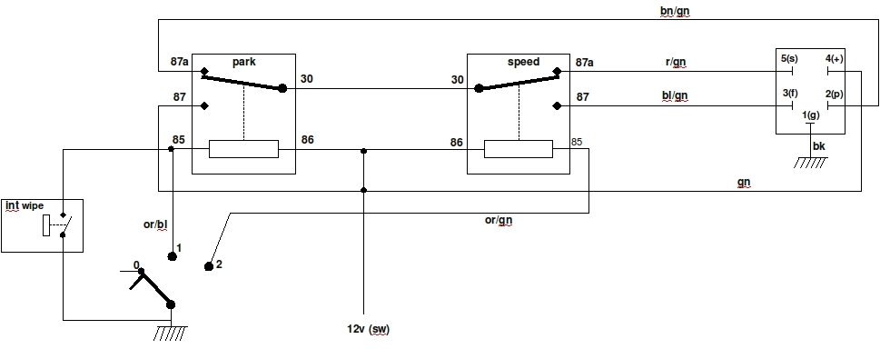
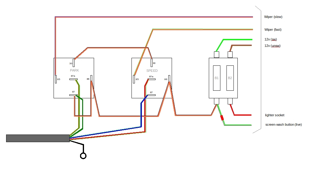
The only disadvantage of this circuit is that it requires a car light switch to work properly (often described as 'On - On - Off', or 'Off - sidelights - sidelights+headlights') - this operates one relay in the first position (slow speed), then both relays in the second position (fast speed). When set to the 'Off' position the first relay makes the connection to park the wipers. This sort of switch can be found in all sorts of shapes and sizes, including toggle, lever, pull and (my choice) rotary. It may be possible to use a conventional switch by using a diode to hold the "park" relay on when the "speed" relay is operated - but I haven't experimented with that.
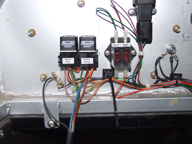
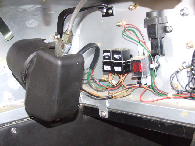
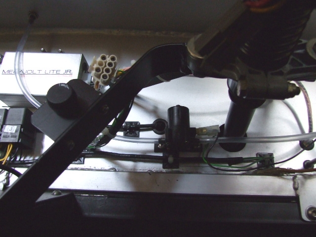
The wiper rotary switch and the washer push switch were mounted on the dashboard near the steering wheel, and the relays were mounted on the passenger side of the firewall near the wiper motor. An additional fuse holder was also mounted near to the relays - the second fuse was used for the dashboard lighter socket (only used for battery charging and as a 12v power supply for on-board equipment).
There were 2 main concerns when installing the wiper mechanism: the position of the wiper wheel boxes and the mounting for the motor.
It is necessary to get the wiper arms and blades before trying to locate the wheel boxes. I bought a pair of Tex adjustable arms and matching 8" blades, to allow myself the greatest flexibility. The wipers were to park on the left (passenger) side, so one set was used to guestimate the correct position of the passenger-side pivot point, putting the top of the wiper a reasonable distance from the edge of the frame. The wiper was then swung around to check that the tip would clear the screen frame at the top of its arc. The end of its travel was not a problem as this was going to be mid-screen.
The driver-side pivot point is a bit tougher to locate as that wiper was constrained at both ends of its travel, from the park position round to the side of the frame. This was estimated by putting the passenger-side wiper into its probable end position and putting the driver's wiper parallel to it. After much experiment the final values were:
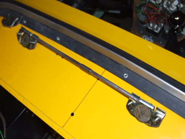
The wheelbox spindles are tilted towards the front of the car, so the hole has to be oval; a cardboard template was made that fitted the spinde and its spacers nicely, and this was transfered to a piece of steel sheet the same thickness as the scuttle skin (for durability). The steel template had guidelines scribed in the top to aid with location. This template was placed in both locations and a scriber used to scratch the shape in the paint; the hole was then drilled and filed to shape, until the wheelboxes fitted correctly.
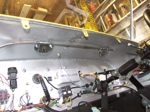
Both wheelboxes were then fitted with the gears up and the spindles down, to allow the centre tube to measured for cutting. The tube was 90mm too long, so needed shortening. The traditional way is to cut the excess off one end and re-make the flare, but I wasn't confident that I could make a decent flare and still get the correct length, so I cut 90mm out of the centre, tidied up and chamfered the cut edges, and a snug-fitting steel sleeve made to fasten the two halves together using Loctite. The wheelboxes and tubes were assembled and fitted into their correct locations.
This left the heavy wiper motor dangling under the scuttle, so a hefty support bracket was made that fastened between the top of the firewall and one of the scuttle fastening screws. The motor was bolted to this bracket using the correct rubber-padded U-bolt with a firm rubber pad underneath - both came from Ebay (originally they were Mini fittings). The rubber helps to reduce the motor noise - probably not a significant issue in a Locost!
Once everything was firmly bolted in the wiper arms and blades were fitted and the whole assembly tested: a quick spray of water on the screen made it easier for the blades to move (don't try it with a dry screen). Happily, everything worked first time!
As with everything else concerned with this windscreen installation, there were issues and problems - mainly to do with the lack of space for the washer bottle. I managed to find a compact bottle and holder of the type originally fitted to a Mini, with a bracket to match. Unfortunately the bracket made the bottle stand away from the mounting surface just enough to make the bottle foul the bonnet, so I had to make my own.
The pump I bought could not lift water (few can) as it was the type normally fitted near to the base of the water reservoir. In the end I decided to put the water bottle in the engine compartment, on the side of the pedal box. The water pipe went through the firewall to the pump, which was mounted on the passenger side of the firewall. This also made the electrics and pipe runs much easier.
Having a windscreen HAS made the car far more convenient to drive, allowing me to climb in and drive without having to don a crash helmet, windproof jacket and motorbike gloves. I am sure that its aerodynamics have been compromised - but a seven-style car has the aerodynamics of a house brick anyway. It will probably reduce my maximum speed, but as I rarely drive above the national speed limit that's not a significant issue for me.
The main lesson I have learnt is that the screen and washer installation would have been far simpler at the time of the original build, even if I had taken everything off for the SVA/IVA - it was much harder doing it retrospectively.