Modern sevenesque cars are usually fitted with motorcycle front wings rather than the old-fashioned 'clamshell' wings. The motorcycle front wings are small, tidy, and don't have any nasty aerodynamic tendencies. However, they do have one significant problem - their stays tend to break due to stress fractures. The main problem is that each wing is only supported on one side and tends to bounce up and down: some stay designs are better than others, but eventually the vibration will concentrate on a stress point such as a weld, a fastener or a change of shape or section. After a period of time (varying according to the stay design) the stress concentration will start to crack the metal, and eventually break it. In my case, the edges of the break showed the classic signs of stress fracture - curved, shell-like shapes going across the broken surface from one edge. It was also the nearside wing stays that always broke, as they were the ones that suffered the most punishment from kerb-side potholes, drain covers and so on. I was lucky that only one of my stays would break, leaving the wing flapping on the remaining one; other people have had their wings fly off completely, only to see them run over by a following car.
There are a few possible solutions to this problem:
I decided to try the third option, having seen it successfully implemented by another builder, Dave Greeves.
That builder's elegant solution was to replace the centre cap of each front wheel with a new cap that is securely fixed inside the centre hole. This new cap supports a ball bearing in a holder, and a bolt is fixed into its inner race. The outer stays are fastened to the bolt with a nylok nut. One thing rankled with this design - the front stub axle is rigidly fixed to the same suspension upright that supports the inner stays, and if I could fix the outer stay support to the end of the axle then I wouldn't need a bearing.
I had a good look at ways of fitting something to the end of the stub axle, but realised that there were several significant issues that couldn't be ignored:
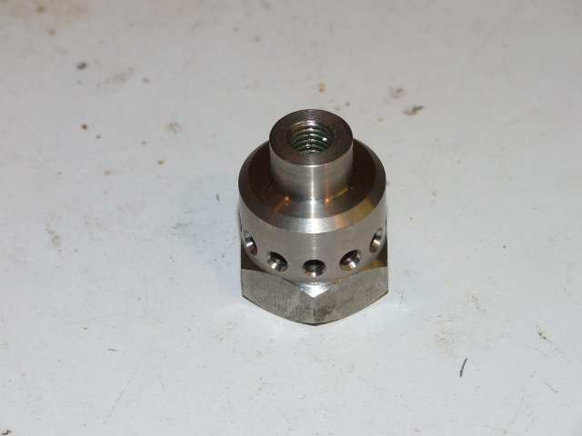
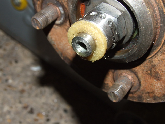
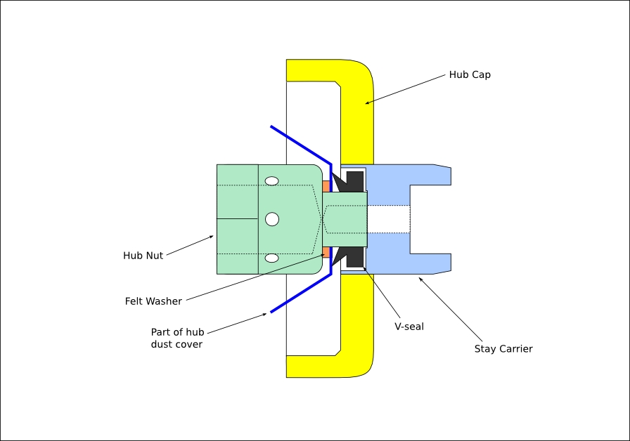
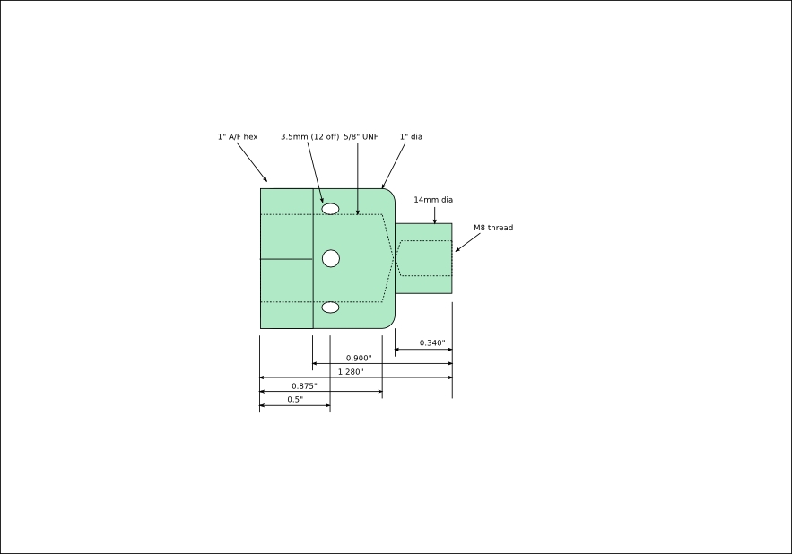
In the end, I decided to see if it was possible to overcome these issues. After much head-scratching and doodling I came up with a design that uses a replacement hub nut made from hexagonal stainless steel, machined in the lathe to provide an extension to support the stays. This design uses the standard dust cap with a 15mm hole drilled in it, and various seals on a 14mm shaft to keep the muck out. Originally I had intended to use V-seals inside and out, but there was insufficient space inside the cover so I used an oiled felt washer inside and a V-seal outside. Both of these work very well when there is some radial mis-alignment - it is impossible to get the dust cap perfectly aligned every time it is fitted, and the wheel bearings also have a small amount of play (by design), so some latitude is always required. The new hub nut has a circle of holes near its base so that a cotter pin can be fitted.
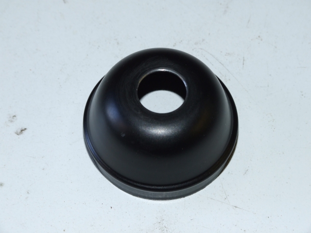
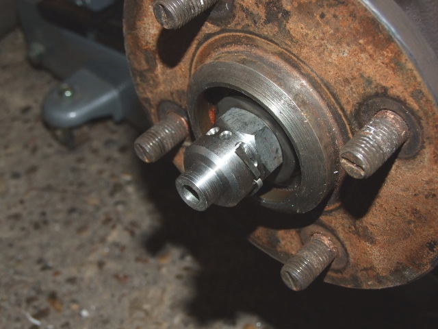
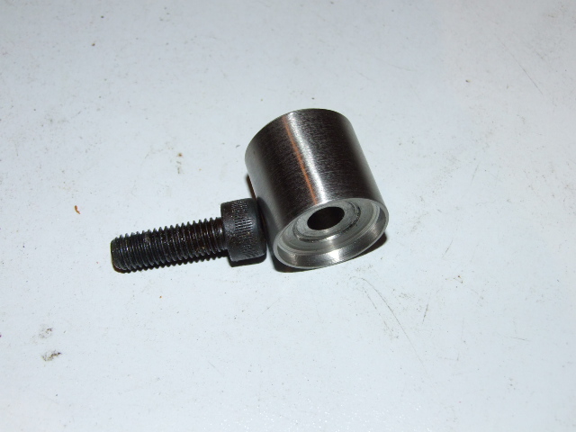
First the new hub nut was fitted, adjusted and secured with a cotter pin, then the felt seal was added. This was followed by the hub dust cover, then the v-seal. The v-seal would normally stay put on the shaft, but as backup the stay carrier both supports it and provides it with some protection. The stay carrier was held in place with an M8 socket cap-head screw and a spring washer. Note that the screw does not need to be tightly fixed - only sufficient to stop it coming undone.
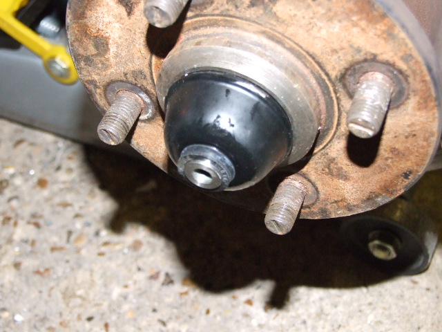
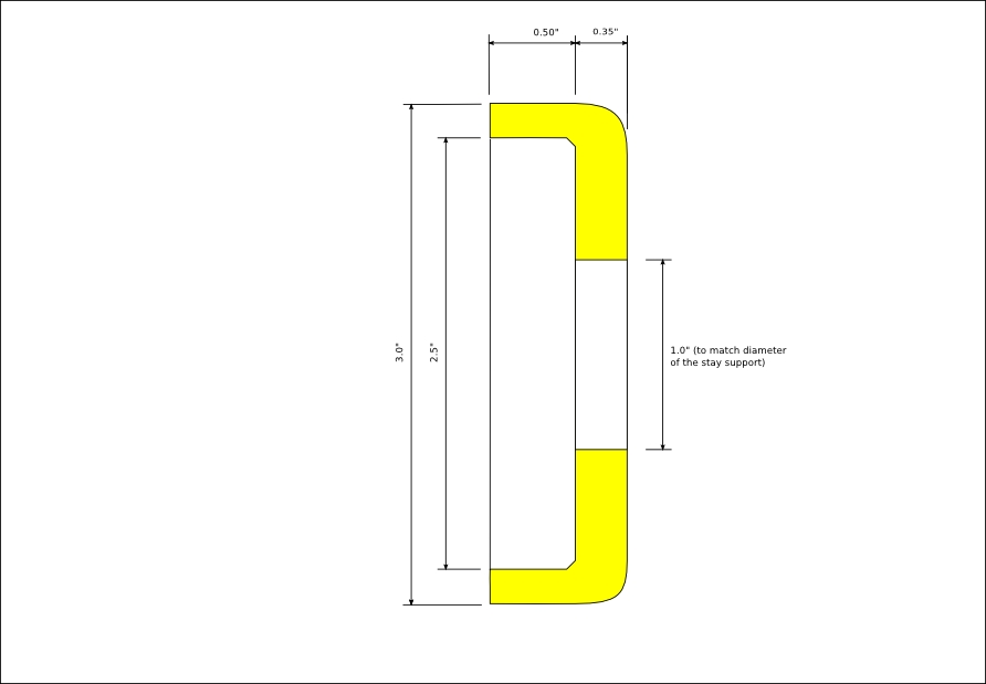
Plastic was chosen for the 'hub cap', both to avoid corrosion and to reduce any risk of scratching the wheel. I was fortunate in that I was donated some samples of plastic used by professional model makers - it's a very hard and tough polyurethane that machines beautifully. This was designed to be glued onto the stay carrier, so it wouldn't rotate with the wheel - it's not obvious, unless you look closely. It also means that removing a wheel is very easy, as the hub cap comes off with the stays.
Any accidental impact on the support is likely to destroy it, but the wheel and axle should not be damaged as the M8 screw forms a deliberate 'weak point' where the stay carrier meets the hub nut shaft.
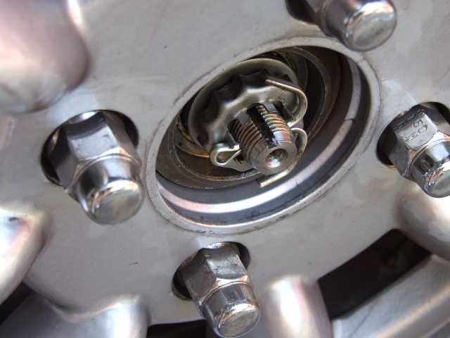
The wheel hole and protective hub cover were measured to get the basic layout of the available space. The following picture shows that there is only a little space available.
The following diagram shows how the components are arranged:
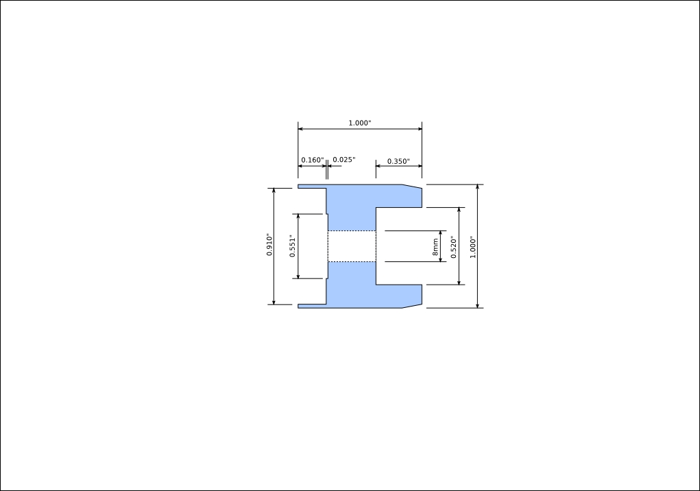
This was then broken down into detailed drawings for the two components:
Finally a decorative hub cap was designed to finish everything off:
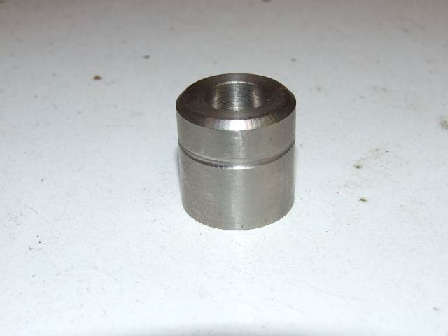
The hub nut was a relatively simple piece of lathe work, but the correct machining sequence had to be followed. The material I used was 1" A/F hexagonal stainless steel bar.
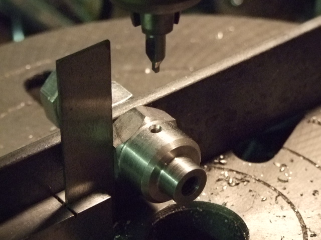
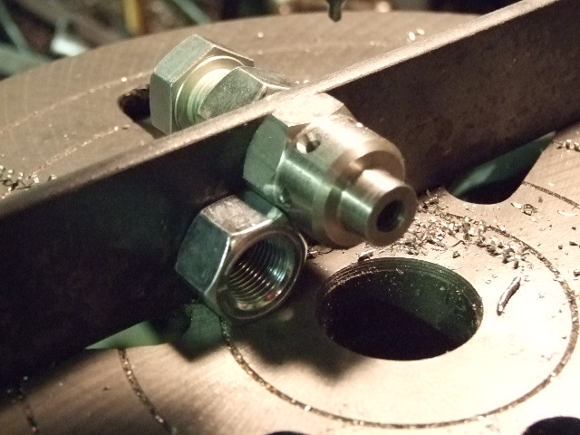
This was followed by drilling the 12 evenly-spaced cotter pin holes, using a jig bolted to the baseplate of my pillar drill. The jig was set up so that the holes were exactly the correct distance from the mounting face of the workpiece (0.5") and exactly central to its diameter. Six holes were lined up by ensuring that each vertical face was at 90 degrees to the baseplate (using a square) and the others at 60 degrees (using a spare nut between the baseplate and a face of the workpiece). Each hole's location was 'spotted' with a centre drill to locate the drill bit - there was a risk of the drill bit wandering on a smooth curved surface. This technique is shown in the following pictures:
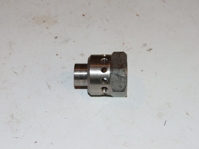
There was nothing complicated about machining this component to the diagram, apart from the following:
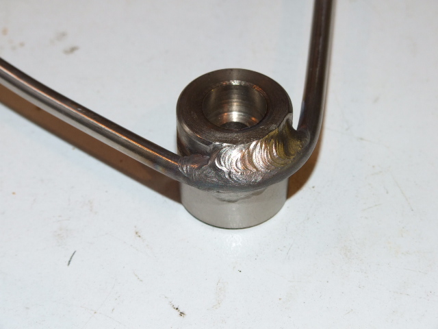
The stays were made from 5mm diameter stainless steel round bar. Each pair was made from a single piece of rod, bent into a 'V' with a radius to match the the stay carrier, and then TIG-welded to the stay carrier. The stays were bent to suit the wheel and mudguard positions with the aim of clearing all the moving parts, but without them sticking out too far and risking accidental damage.
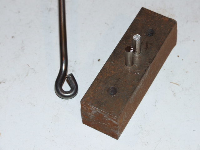
Each stay was fastened to the wing using tabs fixed to the existing inner stays, and the connection to the tabs was made using loops formed on the ends of the stays. The loops were made while the steel was red hot, using a simple bending tool held in the vice. This tool had two 5mm pegs held in a block of steel with their centres just over 10mm apart - with this device each loop could be formed in about 5 minutes.
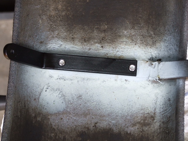
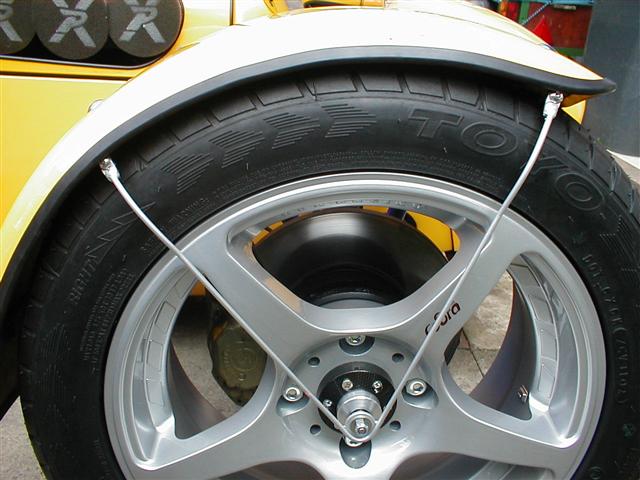
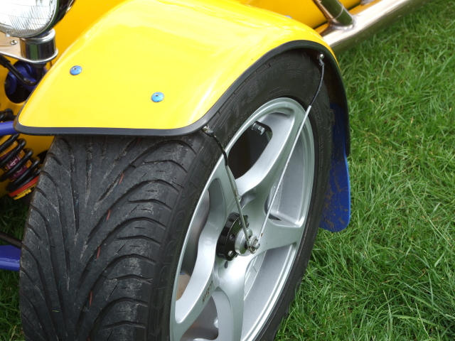
The following pictures show the wing stays in place. I like them, even though I know that they're not to everyone's taste! It is fun watching people trying to work out how it works though...
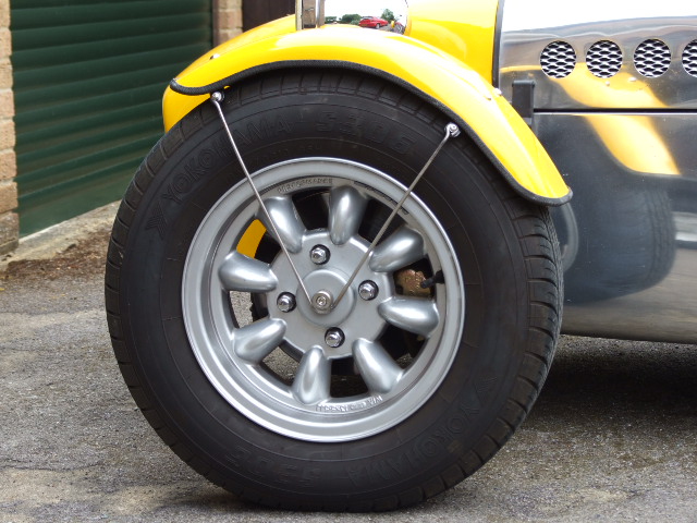
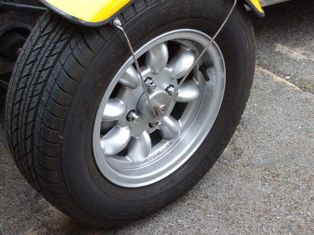
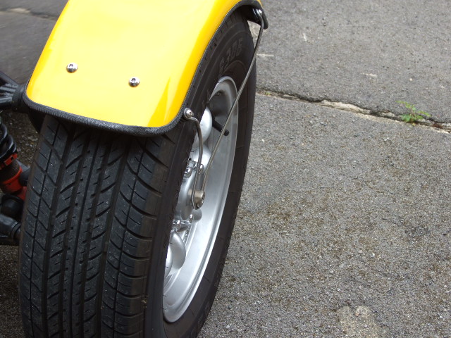
Having tested these on the road, it is clear that the wings no longer flap around at all so (hopefully) the chances of the original stays cracking should be remote - time will tell.