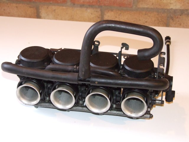
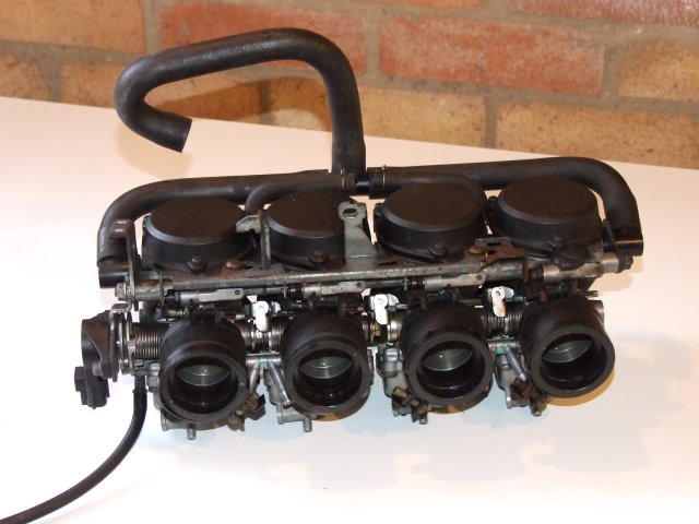
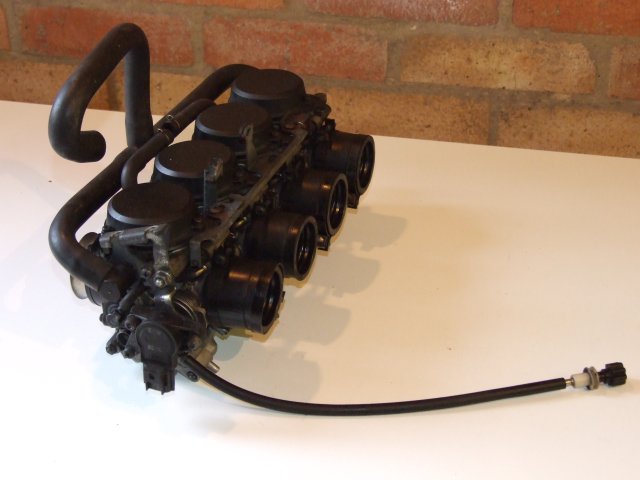
It seems that almost any set of carbs will do, from bikes of capacities from 600cc up to 1200cc or higher. Unfortunately, the larger carbs cost a lot more money, but thankfully the ones from 600cc bikes are very suitable for 4-cylinder car engines with modest states of tuning. I ended up buying a set of Honda CBR600F-X carbs off eBay for Ł15 + postage. Fortunately the package included the Throttle Position Sensor (TPS), the inlet trumpets and the manifold connectors, which saved a load of hassle.
The one main consideration was the orientation of the carbs in the original bike, as they come in 2 variants - vertical or horizontal. In reality they are usually to be found nearly horizontal (maybe pointing upwards by 20 degrees, as on the Suzuki Bandit) or approaching vertical (pointing upwards at slightly more than 60 degrees, as on the Honda CBR600). Having bought CBR600 carbs, I had to compromise with a manifold with a fairly modest angle (more later).
These are Keihin carburettors, commonly found on various Japanese bikes. They operate in a similar way to SU carbs.
Any builder who uses bike carbs has to make a decision; whether to split the carbs and space them to suit the engine, or to leave them as they are and make (or buy) a manifold to connect to the engine. The main advantage of leaving them un-split is that all the linkages and connectors continue to work as intended, and no modifications are required. The main disadvantage is that the manifold requires some difficult bends and therefore is either hard to make or expensive to buy.
The main advantage of splitting the carbs is that the manifold is fairly cheap and easy to make. The main disadvantage is the amount of work required to space the carbs and still make them work. Being awkward, this is the route I chose!
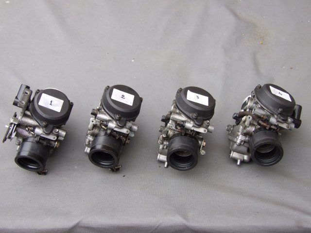
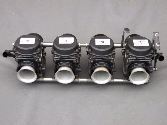
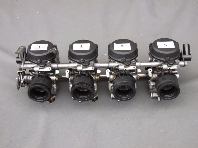
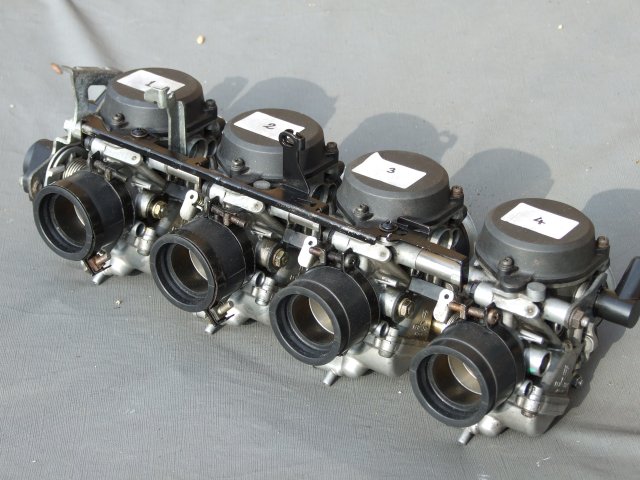
The CBR600 carbs were fairly easy to split, with just 2 long tie rods holding everything together. Once the nuts were undone it was only necessary to pull the individual carbs apart - but this can be quite a challenge. I found that some connections were slightly corroded and required some 'persuasion' to separate them, but they all came apart in the end.
The first and most important step before separating the carbs was to number each of them, as they must be reconnected in the correct order. The other important task was to pay attention to what connects to what, especially when the carbs were pulled apart. After all, they had to be put back together at a later date!
The required amount of spacing was worked out using a spare Kent inlet manifold gasket - the outer pairs of cylinder head inlets were 99mm between centres, the inner pair 93mm (but see notes later). All of the bike carbs were originally 75mm between centres. All spacers, connectors and inlets were modified using these parameters.
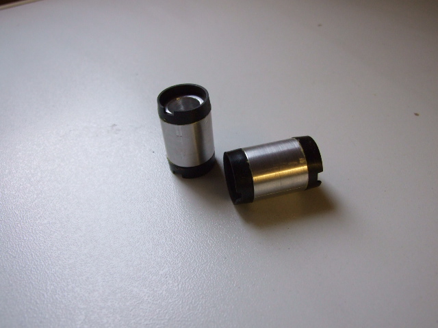
Originally the carbs were keyed together with stainless steel sleeves between each one, where the tie rods went through. These were 5/16" diameter, 20mm long (apologies for the mixed measurement standards - the carbs were full of such weird combinations!). These were replaced by stainless steel spacers turned up on my lathe. The outer pairs were made to add 24mm between the carbs; the inner ones were made to add 20mm.
Note: in theory, the inner carbs should be separated by 18mm but this didn't work - adding a washer made the spacer up to 20mm, which separated the inner carbs correctly.
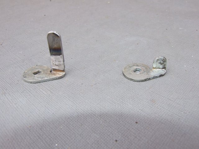
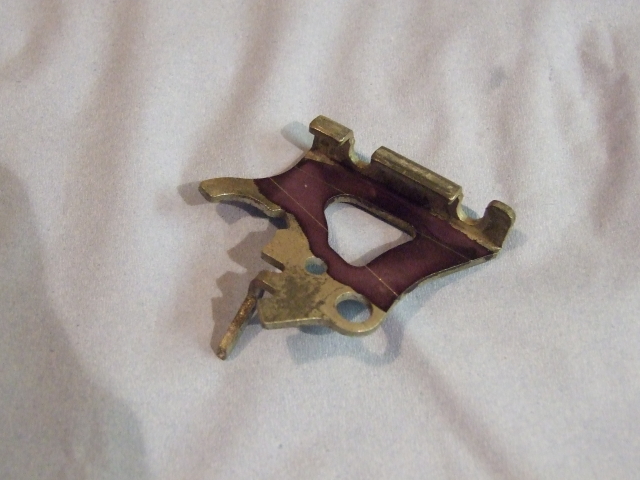
The throttle linkages no longer worked once the carbs had been spaced apart, which meant that the tabs on three of the carbs had to be extended. The outer ones required an additional 24mm, and the inner one an extra 20mm.
I first tried silver-soldering an extension onto the tab, but it proved to be almost impossible to keep everything in line. This idea was eventually scrapped, and I resorted to MIG-welding the extension pieces on. Each piece was clamped to a steel block to keep everything aligned, then the weld made and a grinder used to tidy things up. Finally the pieces were tidied up and oil-blacked to improve their rust-resistance.
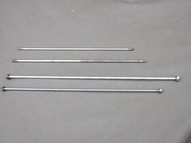
The original tie rods were now too short, so new ones had to be made. One was 6mm diameter, the other was 5mm diameter. For the moment I am using threaded rod, but I intend to make ties from solid round bar once I can get some stainless steel in the correct diameters.
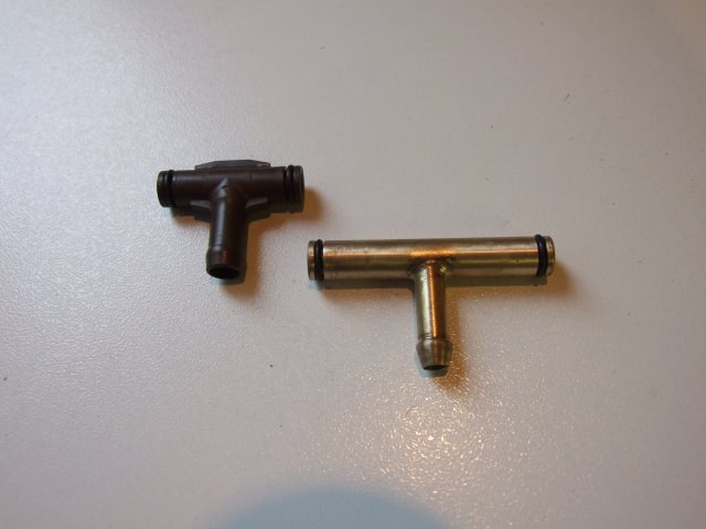
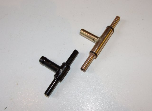
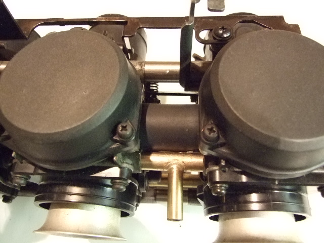
Each of the outer pairs of carbs were originally fed by a common 'T-piece' made of plastic, with o-rings to make the seal with the carb bodies. As these were now too short, new 24mm longer ones were made on my lathe. These were made from 2 pieces of brass, silver-soldered together.
The CBR600 carbs have a 'Starting Enrichment' (SE) system that adds more petrol to the mix when operated. This is in place of a choke butterfly, although the effect is the same - a richer mixture for a cold engine.
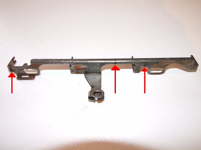
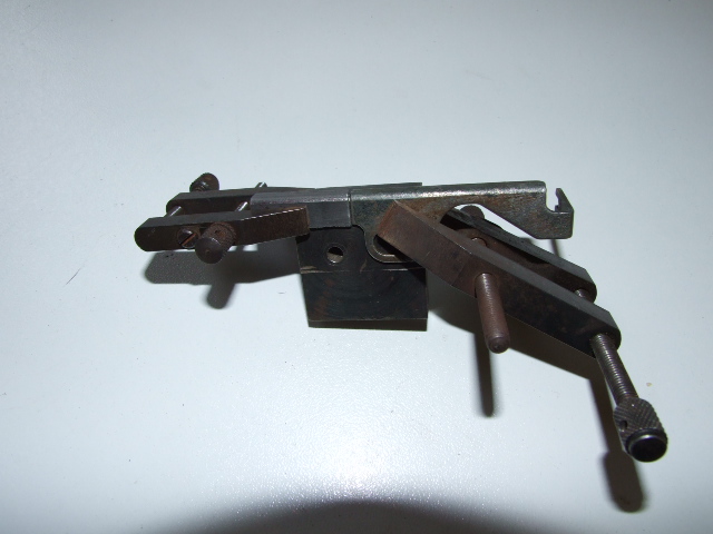
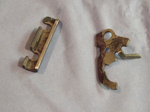
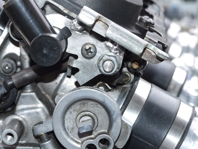
The linkage was sawn into 4 pieces in places shown in the picture above. The cuts were tidied up with a file, ready for welding.
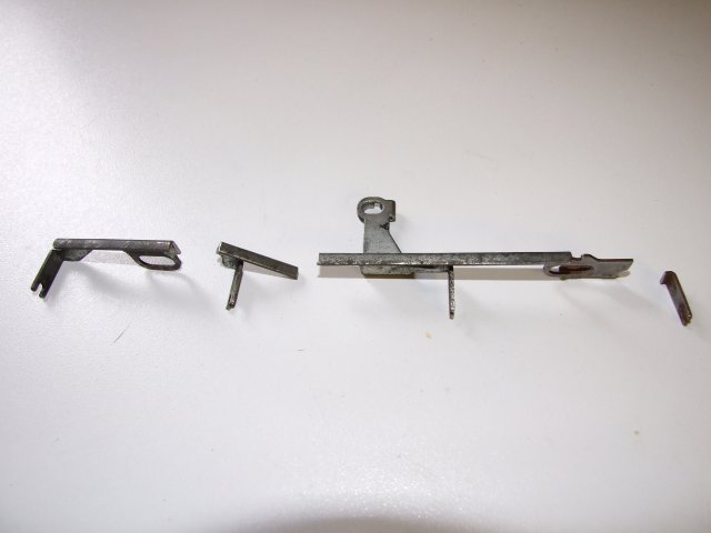
Each piece was then clamped with its extension onto a block of steel that has a straight and square edge, ready for welding.
After welding all the pieces back together and testing for fit, the whole item was tidied up and oil-blacked, then all the carbs were fitted together again.
The carbs came with a fairly complicated system of vents and bits of tubing. Some of these will be ignored, e.g. the carb heat system for de-icing. There are 2 other connections to be dealt with:
This is a system that originally allowed the carbs to be used with a catalytic converter - when the engine was running correctly the top of the float chamber was supplied with air at atmospheric pressure, which allowed the reduced pressure in the carb venturi to suck up petrol. If the ignition system stopped working a solenoid was actived, which connected the sub-air inlet to the inlet manifold. This put equal pressure in the float chamber and carb venturi, with the result that petrol was not sucked up into the carb. This stopped unburnt fuel going through the engine and polluting the catalytic converter.
As these carbs are not being used with a catalytic converter the sub-air feed can be left open to the atmosphere. This was done by simply replacing the black T-pieces that connect the sub-air inlets on each of the outer pairs of carbs. Copies were made on the lathe, 24mm longer, and they were fitted with an air filter foam cover.
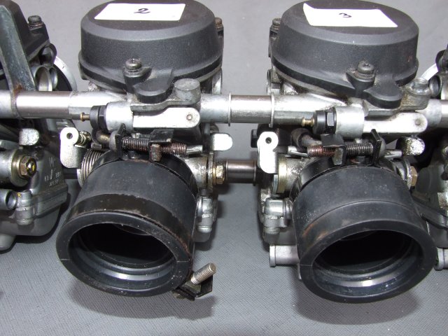
The outer pairs of carbs had a rubber sleeve that sat between each carb's slide chambers on the non-vacuum side. The outer carbs had a hose connector that was connected to a clean air supply (originally 2 small air filters on the bike's air box), and the air joint rubber allowed that clean air to be shared between 2 carbs. This supply of air allowed the rising and falling of the diaphragm as the vacuum inside the chamber varied.
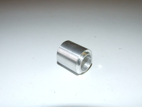
Each rubber sleeve was split around its centre and the 2 halves glued to a length of machined aluminium that was just long enough to fit between each outer pair of carbs, across the place where the sleeve once fitted. Once the fit was checked, the sleeves were covered in adhesive heat-shrink tubing that securely fixed the 2 parts of the sleeve.
IMPORTANT! If you try this, make sure that the 2 notches on each half of the sleeve are aligned correctly.
When it came to the time when the carbs were test-fitted to the engine it was clear that there wasn't enough room for the throttle cable; the gap between the existing cable mount and the car's nose cone was too small for anything other than a very tight 90-degree bend, which would have restricted the inner cable.
After some deliberation I decided to shorten the cable fixing mount by about 1cm to allow the fitting of a gentler bend. The mount was marked out, sawn and clamped for welding.
| [Bike carburettor menu] | [Making the manifold] |