After respacing the carbs I decided to go the whole hog and build my own inlet manifold. I did not have the welding equipment required for aluminium, nor the skills to use it, so I did all the fabrication and jigs ready for a professional to finish.
A backplate is required to:
I made a number of mistakes with my first attempt at a backplate: originally I decided to use 15mm aluminium bar, but soon found out that (a) it's hard work sawing and drilling such thick material, and (b) I was told that it is hard to make a presentable weld between 15mm plate and 3mm wall tubing. I also tried to use a tubular saw to cut the large holes, and found out just how inaccurate they can be (a 41mm saw gave me a 42mm hole). Other dodgy decisions made me decide to chalk up the first attempt as a 'learning experience' and to start again. The next attempt used a length of 10mm thick bar, just over 60mm wide. Apart from some shaping on the corners, this was left whole for maximum strength and rigidity.
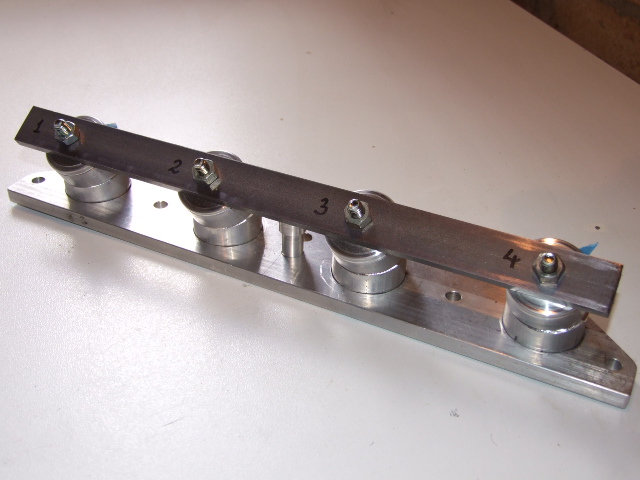
The first task was to draw up the position of all the holes on a large sheet of paper, using a new gasket for some measurements (the location of the stud holes, for example) and direct measurements off the spaced carbs and cylinder head for the remainder. All of these measurements were double-checked thoroughly before marking out. Once I was confident that the measurements were correct, I covered the metal with blue marking-out ink and set out all the hole centres. After yet more double-checking these were centre-punched and a pair of dividers used to draw all of the holes; the large holes also had a smaller-diameter circle drawn inside, which was to be used for locating chain-drilling holes.
Once each circle of holes was drilled, a small chisel was used to cut the links between each hole, then the remainder was knocked out. The edges were cleaned up with a rotary file in an electric drill, followed by some fitting with a half-round file to ensure that the tube was a snug but fairly loose fit in the hole.
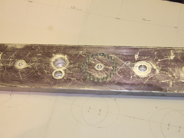
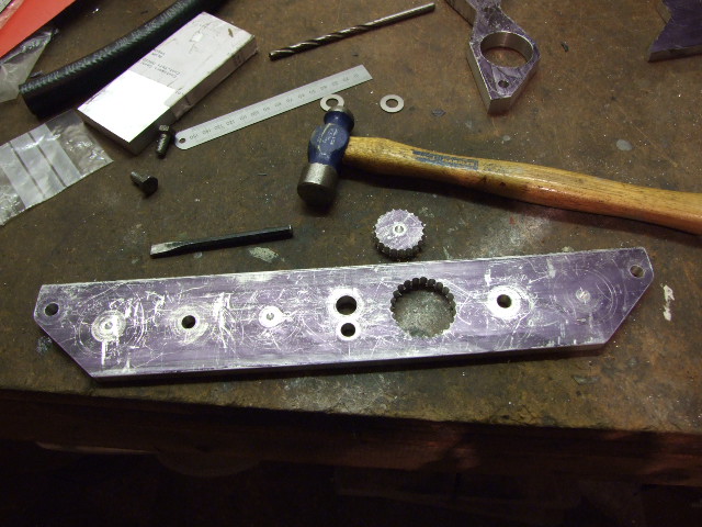
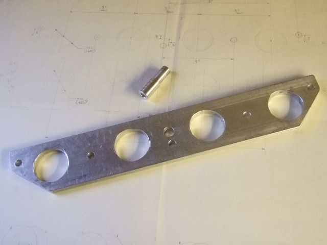
The backplate was cleaned up after drilling all the holes and all burrs removed. The corners of the bar was shaped slightly to tidy it up.
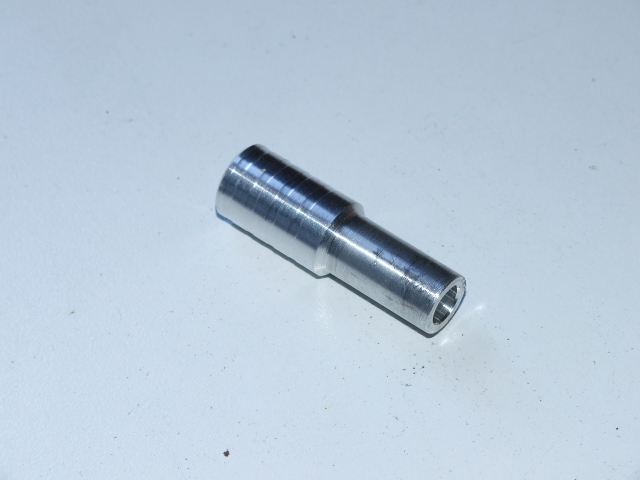
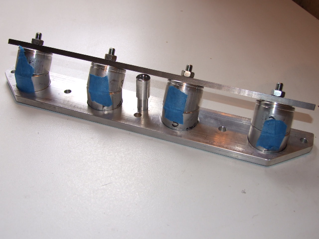
The Ford Kent engine has a water coolant connection through the inlet manifold. This was replaced by a simple turning made out of aluminium bar. The only significant features are the slight ridges to help to keep the hose on, and the reduced diameter that allows room for the manifold stud nut to be tightened.
The tubes were made of 15/8-inch, 10-SWG wall-thickness aluminium, which was an exact match for the carbs' rubber connectors both on the outside, where the connectors are fastened and for the bore inside. This meant that there would be little disruption for the flow of the air-fuel mixture.
The length of tube bought had a fairly scruffy end, so this was used for experimentation. The result was a set of reference patterns or templates to be used for the real pipework.
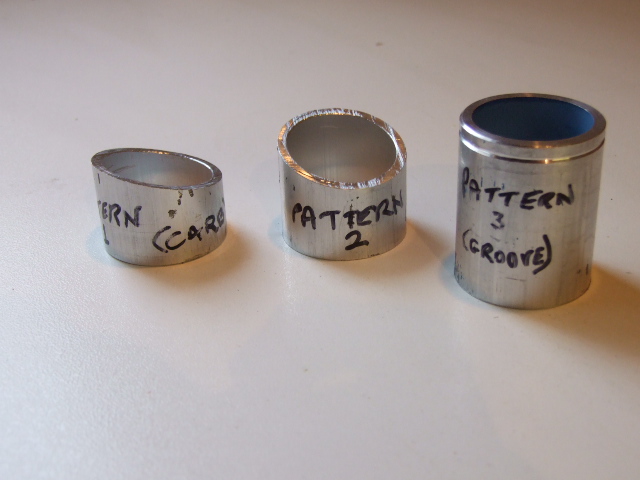
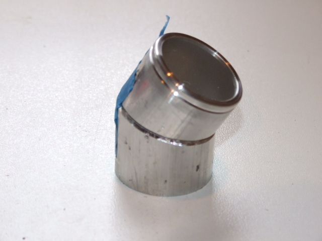
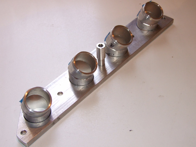
These experiments showed that I needed a 30-degree bend in each pipe; this was produced by cutting across at 15 degrees, tidying up the cut edges, then rotating one piece by 180 degrees. The grooved pattern was designed to match the rib inside the rubber connector - this formed an air-tight and mechanically strong joint once the clamp was tightened.
The machining sequence was as follows:
Each pair was then matched up to get the 30-degree angle, and 2 dots punched to make matching the pieces easier later on. Each was lettered to ensure that the correct pieces were paired, then taped together for convenience. The matching faces were chamfered at approximately 45 degrees, to 50% depth, ready for welding.
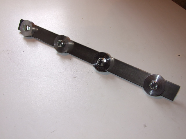
The final requirement after welding the carb connection tubes was to ensure all were parallel and in line prior to welding them to the backplate. A jig was manufactured to ensure that they could be located correctly.
At this point all parts were ready for welding...
Once everything was ready for welding I took it to a friend who was also a professional welder. I did this because I didn't think that I had the skills and tools to do it myself - and how right I was!
First of all the inlet tubes were tacked together in the correct orientation, then fully welded. The backplate was bolted to an old crossflow cylinder head to keep it flat during welding, as anything that gets welded will try its hardest to warp as it cools; distortion is a fact of welding life that can't be avoided. The now-welded tubes were inserted into their holes, and the alignment jig fitted.
Then the tubes were welded in place - and I found out what was involved in welding 10mm thick aluminium! To keep the heat up it was necessary to set the TIG to about 165 Amps, and by the time the welding was completed the whole cylinder head was too hot to touch for at least 30 minutes. Never under-estimate the amount of heat that the workpiece will absorb in a job like this...
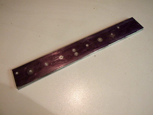
Still, it looked very nice once it was finished.
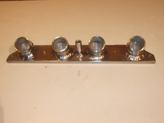
Although the cylinder head kept the backing plate reasonably flat, there was a bit of distortion. This was removed by sticking some emery cloth onto a flat surface (a marble slab!) and working the manifold over it like a wood-worker's plane. I started with quite coarse grit, and worked down to fairly fine grade. The scratches on the underside give a good indication of the high and low spots. It took quite a few hours spent at random times to get the back flat enough; I could have got it skimmed at a machine shop but (a) it was inconvenient and (b) it would have cost too much.
| [Setting up the carburettors] | [Fitting the carburettors] |