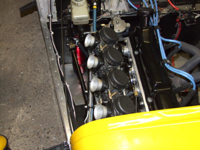
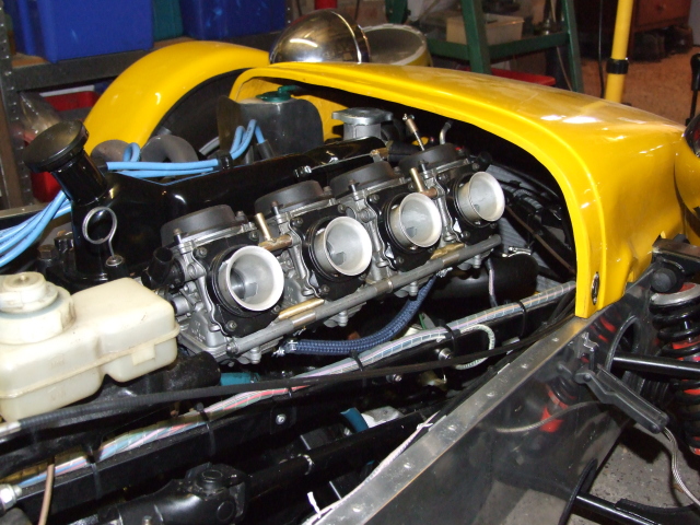
This part deals with the installation of the carbs, together with all the extra jobs that seemed to come along with them.
The following jobs had to be done to enable the engine to work properly after installing the carburettors.
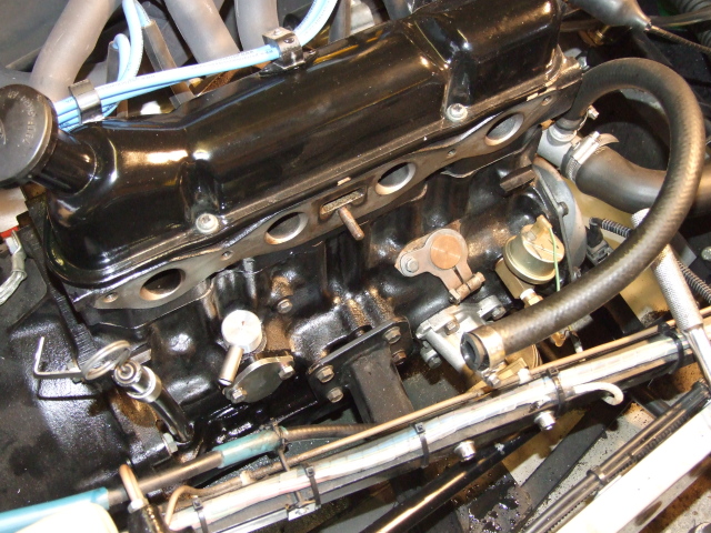
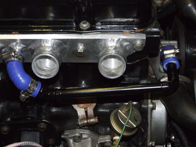
Originally the oil fumes from the crankcase were routed into the inlet manifold via a Pressure Control Valve (PCV). As the new manifold had 4 airways instead of 1 it was no longer a practical method. The PCV was replaced with an outlet supplied by Burton Performance, and a pipe was taken to a suitable catch-tank.
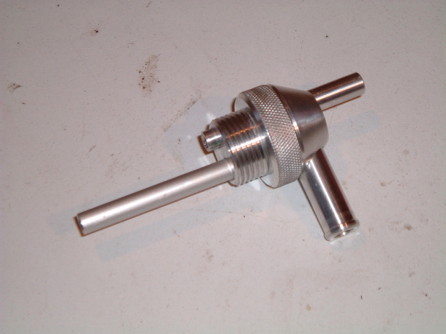
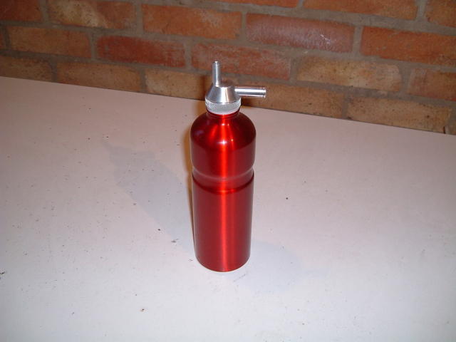
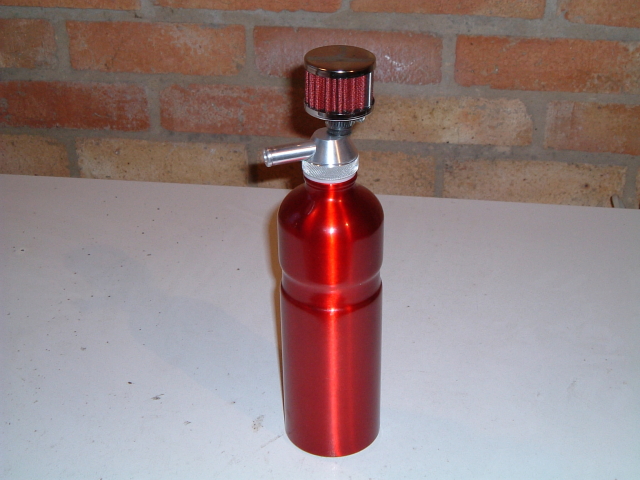
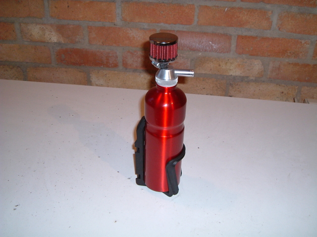
This catch tank was made from an anodised aluminium cyclist's water bottle, as found in places like Halfords. A threaded bung was made to screw into the top of the bottle; the neck of this bottle had a very strange thread of 26mm x 2mm. Two aluminium pipes came out of this bung - the side inlet, which had a half-inch diameter end for the hose from the crankcase breather, and a straight vertical pipe with a 9mm diameter end for a breather filter.
The bottle was fitted to the bulkhead using a water bottle bracket, also from Halfords.
UPDATE: This tank didn't work very well in practice. On reflection, an insulated bottle is unsuitable for a catch tank as by its nature it prevents the oil vapour from condensing on the inside of the tank and settling to the bottom - in my arrangement the oil vapour just passed straight through the tank and fouled up the filter. A simple single-sided container would be far more suitable, particularly a commercial one with a sight glass on the side and a drain underneath to empty it out periodically.
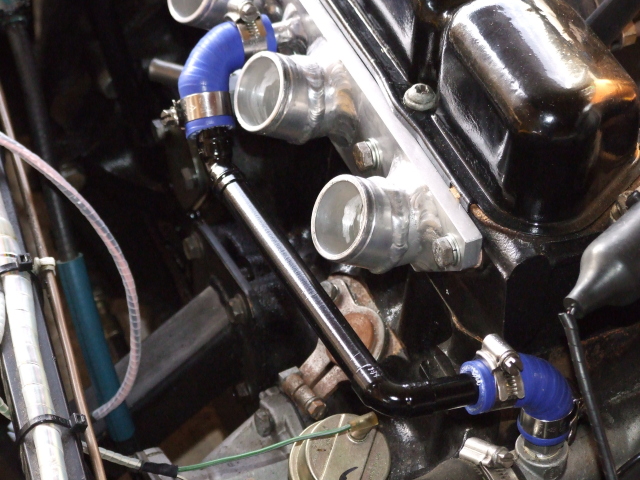
This could have been done with a slightly longer piece of coolant hose, but that is fairly rigid due to its thick reinforced wall. It would have been in the way of the carbs, and would have looked untidy. Instead a shaped rigid pipe was fabricated out of copper tube and soldered elbows, held in place with short lengths of flexible coolant hose bends and jubilee clips.
A set of universal throttle cables suitable for Honda bikes was bought off Ebay; this had a selection of ends, fittings and adjustors that made the conversion fairly easy. The only additional parts were an adaptor to fix the narrow cable to the existing large hole, and a Ford-style accelerator pedal connector for the end of the cable inner. Both parts were fabricated out of stainless steel and brass.
.jpg)
.jpg)
The starting enrichment was set up using the original choke cable, which came from a Weber choke conversion kit (similar cables are available from many suppliers).
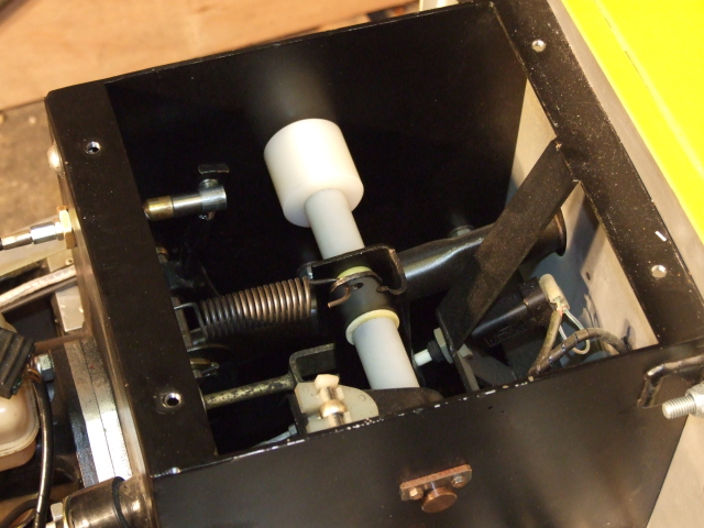
Although this is not an 'essential', it is a very good idea as it helps to prevent possible throttle linkage breakages caused by over-enthusiastic pedal use. It is also one of the safety features that may be required by a SVA inspector.
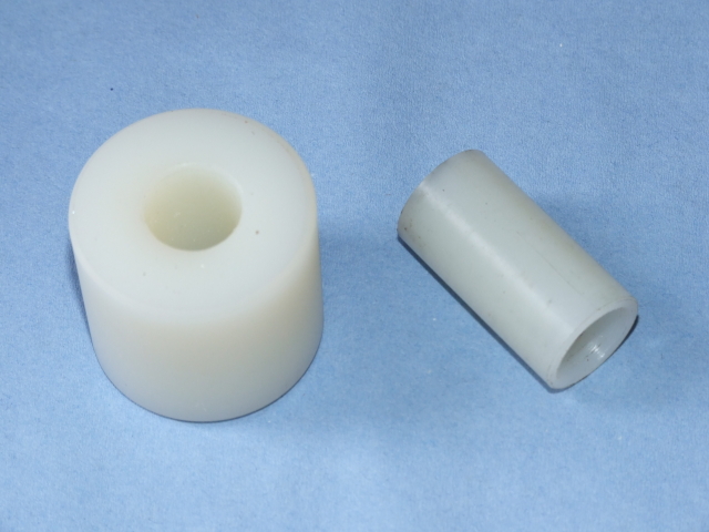
Many people fit a backstop behind the accelerator pedal, but that would have been inconvenient when it came to adjustment. Instead I chose to fit the stop at the top of the pedal in front of the cable connector, where it would be far easier to adjust. It is simply a nylon disc mounted on the spindle used by the clutch and brake pedals. Although its position is fixed, if the cable stretches the adjuster at the pedal end can be moved to make it effective again.
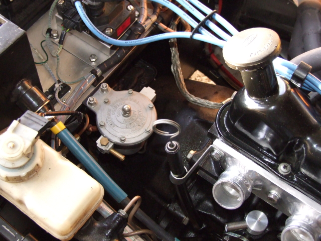
Bike carbs run on a very low fuel pressure of 1 - 2psi, but at a high volume. The existing mechanical fuel pump would have required a regulator, and would be essential for an electrical pump. I decided to buy a Filter King combined filter and regulator off Ebay. When it arrived I was surprised to see how large it was! I found managed to find a suitable space, made a bracket and bolted everything into place.
See later details of subsequent removal of the regulator in the carb tuning section
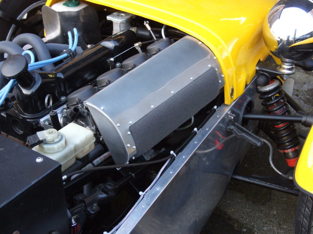
When I first decided on bike carbs I had thought that I would be fitting a sausage filter, but when I looked at the products from all the usual suspects (Pipercross, ITG, K&N) I realised that no stock item would fit into the space available.
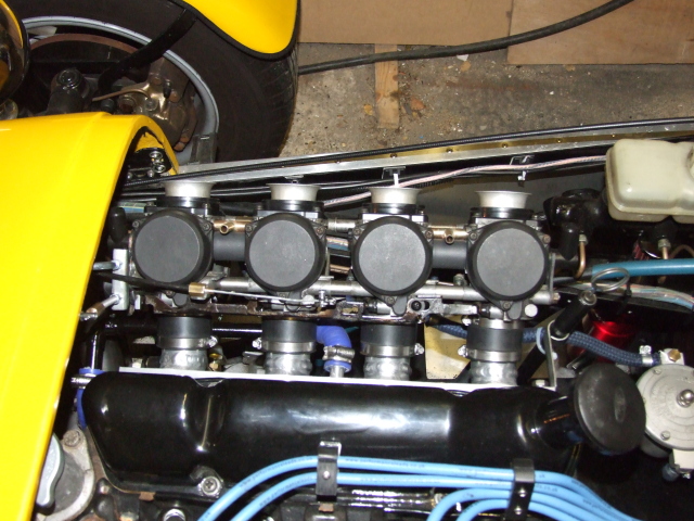
I was then left with the choice of filter socks (had to fit securely), a home-made airbox with a remote filter (space limitations again) or a home-made filter that was smaller than a stock sausage filter (chipolata filter?). I decided to build the last option, using triple-layer foam sheet from Pipercross.
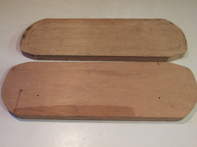
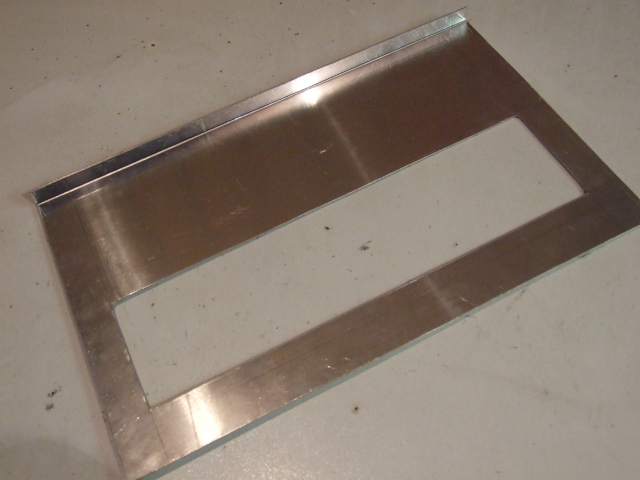
The first task was to make a cardboard template for the body of the filter. Once I was sure that the body would clear the bonnet, and that there was a good chance that air could flow around the filter surface, I transfered its shape to two pieces of thick plywood. The edges of one of these was smoothed and shaped to give a good surface - the other piece is only intended to stop the sheet buckling up during shaping so the edge is less critical. I also cut a piece of aluminium that was about 12mm larger all around. The four 63mm diameter holes for the carb connectors were cut in the aluminium, then the sheet was placed between the plywood formers; all three were screwed together through the carb holes after ensuring that everything was lined up correctly.
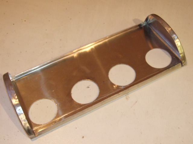
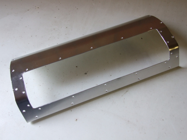
At this point the shaping started by steadily tapping all round the edge of the aluminium sheet, slowly bringing it up to the edge of the smooth former. It was necessary to dismantle the formers two or three times so that the curved ends of the aluminium could be annealed. After shaping the sheet was removed from the formers to reveal the backplate with a 12mm rim all around its edge. Finally I marked the location of the side bends, cut relief slots in the rim, and bent the ends up. The filter body could then be test fitted on the carbs.
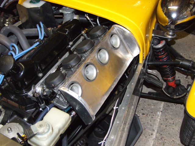
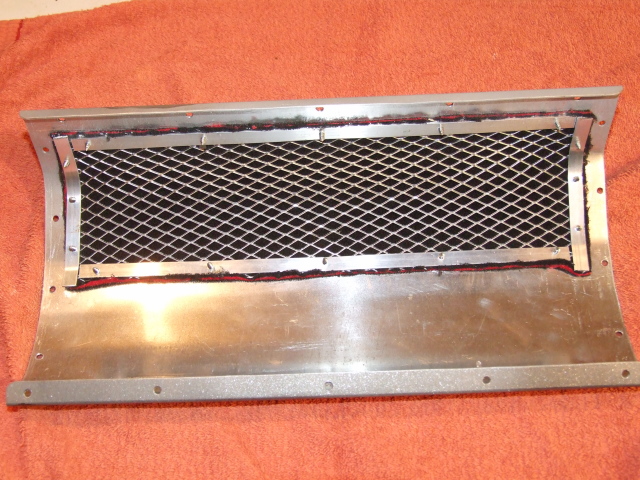
The next step was to decide what to do with the front of the filter holder: to use it as an air-box and fit a connector for a hose and remote filter; put foam across the whole of the face; or put foam across just a part of the face. Each has its own advantages and disadvantages, but in the end I decided to try the third option, mainly because of the risk of fire if a carb should backfire; having a top half of aluminium in front of the carb mouths makes it a little safer. I started by cutting a sheet of aluminium to fit the front off the filter body, allowing for a 12mm lip top and bottom to aid with location. This was then marked with a rectangle in its lower half, about 12mm narrower and higher than the inner lips at the bottom and sides. This rectangle was then cut out and all edges smoothed.
The cover sheet was then shaped to fit the filter body, using self-tapping screws to hold it into position. After ensuring a good fit, four pieces of 12mm aluminium strip were cut to fit around the opening, to be held in place with self-tapping screws. A piece of foam and a piece of backing mesh were cut 24mm longer and wider than the hole in the facing plate and the two were put in place inside the cover. These were held firmly by the four aluminium strips.
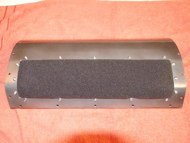
Finally the whole assembly was cleaned up, painted, assembled and fitted.
I could have made connections to each of the inlet manifold's runners, led the tubes into a 'combining box', and then used the existing Megajolt setup.Alternatively I could run 3 wires from the MJ box to the TPS sensor already fitted to my bike carbs, and add 5 or 6 cheap components to the MJ circuit board - I chose TPS.
Although not technically as 'correct' as MAP, it's more than accurate enough for most people.
I decided to fit an electric fuel pump, and chose a 'road' model Facet solid-state model. This pump is supposed to be good for up to 130BHP, so it should be sufficient for this engine. It came as a kit, complete with mounting rubbers, an inlet filter and an outlet.
Fitting the pump was not difficult, once a location had been found. It sits just ahead of the back axle at, or just below, the level of the bottom of the tank; the pump does not have to lift petrol at all.
The whole assembly was bolted to a stout length of steel bar with a cross-piece welded on, which in turn was bolted to the chassis.
I had already run a wire from the fusebox when I first wired up the car, so all that remained was to install a suitable earth point and a 2-way connector.
The original mechanical pump was removed and a cover plate put in its place.
See details of the subsequent pump replacement in the carb tuning section
After declaring that I was going to fit an electric fuel pump, several people advised me to also fit an inertia switch. This is designed to break a circuit when the car is in a bad impact or roll-over, and is commonly used to switch off the fuel pump. I decided to wire it into the existing security circuit so that it would also cut the engine's ignition.
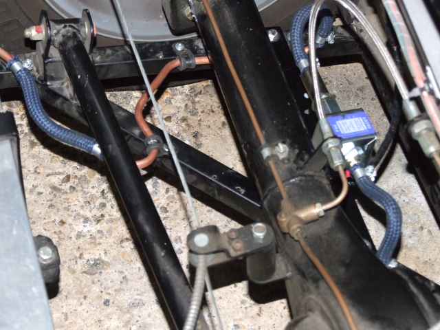
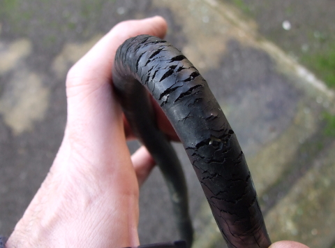
While messing around with the fuel system I realised that the existing rubber pipe, although supposedly to British Standards, had perished badly in just 3 years and needed complete replacement.
I decided to run 8mm copper pipe through the transmission tunnel and between the tank and the pump, using flexible pipe only for the interconnections. This will make checking the flexible pipes much easier in the future.
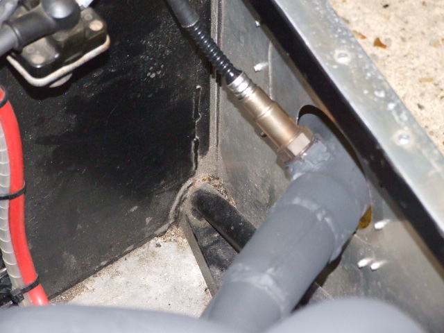
I had decided to fit a mounting boss (with plug) for a wideband lambda/AFR sensor, to allow on-the-road testing of the carburettor mixture. The boss and plug was bought off eBay, mainly because it was cheap (£6) - I could not have made one for the same money. Fortunately it was very well made and well worth the money.
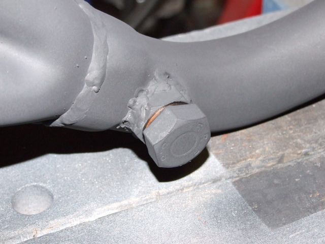
A suitable location was found, just after the final combining point in the exhaust manifold. The Bosch sensor documentation recommends that the device is mounted at 10 degrees or more above the horizontal so that condensation can drain out of the sensor housing. The tube was drilled, the boss tacked in place and then it was fully welded. The following picture shows the fitted sensor - most of the time the sensor is replaced by the plug and copper washer to try to conserve it.
| [Making the manifold] | [Tuning the engine] |